PlyEdit: Import Align Combine
From Headus Docs
| Revision as of 04:34, 13 December 2010 (edit) Headus (Talk | contribs) (→Offset) ← Previous diff |
Current revision (06:44, 16 December 2010) (edit) (undo) Headus (Talk | contribs) |
||
| (12 intermediate revisions not shown.) | |||
| Line 31: | Line 31: | ||
| ; Sculpt : Select which mesh is affected by the sculpting brushes. | ; Sculpt : Select which mesh is affected by the sculpting brushes. | ||
| - | ; Flip : | + | ; Flip : Inverts the surface normals on either the 2nd "red" mesh, or the green selected faces on the first "white" mesh. |
| - | === Offset === | + | == Offset == |
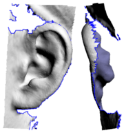
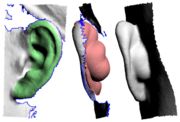
| - | The '''Offset''' tool {{more}} | + | {{img|PlyEdit-ear1.png|Missing Behind Ear}} The '''Offset''' tool is used to add a "back face" to a section of mesh. First {{key|G}} key mark the faces you want to offset, set the thickness amount, then click the '''Offset''' button. The marked faces are copied, flipped so their normals are facing backwards, then each vertex is pushed back in the direction of the surface normal at that point. |
| - | === Mark Intersect === | + | Convex surfaces will balloon out, and concave surfaces will end up self-intersecting if the offset is large enough, so sometimes its a good idea to do an initial offset of about half what you think you want. You can then check the offset surface, maybe even smooth or sculpt it a bit to remove the self-intersecting faces. Click the '''Offset''' button a second time and, because you already have an offset surface created, that surface is simply push back a bit more; there's no copying of faces or flipping of surface normals. |
| + | |||
| + | For example, this tool can be used to add some mesh behind the ears, something that is usually missing from cylindrical type head scans (see {{fig}}). {{img|PlyEdit-ear2.png|Offset Surface}} In {{fig}} you can see that the front of the ear is marked, its offset by around 4 or 5 mm, then the resulting mesh is sculpted and blended in with rest of the ear. | ||
| + | |||
| + | == Mark Intersect == | ||
| The '''Mark Intersect''' tool is used to green mark faces near the intersection of two or more objects. These marked faces could then be voided, and the gap bridged across, to join the two objects together. | The '''Mark Intersect''' tool is used to green mark faces near the intersection of two or more objects. These marked faces could then be voided, and the gap bridged across, to join the two objects together. | ||
| Line 55: | Line 59: | ||
| ; x4 : Same as above, but the initial test is done at 4 times the entered tolerance value. To be used if the faces are quite a bit larger than the tolerance value entered. | ; x4 : Same as above, but the initial test is done at 4 times the entered tolerance value. To be used if the faces are quite a bit larger than the tolerance value entered. | ||
| - | === Plot Error === | + | == Plot Error == |
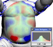
| - | The '''Plot Error''' tool is used to visualize the difference between a pair of meshes. | + | {{img|PlyEdit-error.png|An Error Plot}} The '''Plot Error''' tool is used to visualize the difference between a pair of meshes. |
| # Use the main GUI '''Mesh''' input to load one of the meshes. | # Use the main GUI '''Mesh''' input to load one of the meshes. | ||
| Line 67: | Line 71: | ||
| # Set the error threshold then click on '''Plot Error'''. | # Set the error threshold then click on '''Plot Error'''. | ||
| - | A histogram window pops up, and the first mesh is re-colored in the marked area. Red is where the first mesh is over the top of the second, blue is where its underneath, and solid red/blue is where the error is greater than the threshold setting. | + | A histogram window pops up, and the first mesh is re-colored in the marked area. Red is where the first mesh is over the top of the second, blue is where its underneath, and solid red/blue is where the error is greater than the threshold setting (see {{fig}}). |
| + | |||
| + | {{TOP}} | ||
Current revision
|
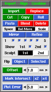
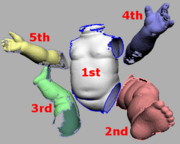
The Import Align Combine panel is used to cut'n'paste pieces of mesh within or between PLY files.
[edit] OffsetThe Offset tool is used to add a "back face" to a section of mesh. First <G> key mark the faces you want to offset, set the thickness amount, then click the Offset button. The marked faces are copied, flipped so their normals are facing backwards, then each vertex is pushed back in the direction of the surface normal at that point.Convex surfaces will balloon out, and concave surfaces will end up self-intersecting if the offset is large enough, so sometimes its a good idea to do an initial offset of about half what you think you want. You can then check the offset surface, maybe even smooth or sculpt it a bit to remove the self-intersecting faces. Click the Offset button a second time and, because you already have an offset surface created, that surface is simply push back a bit more; there's no copying of faces or flipping of surface normals. For example, this tool can be used to add some mesh behind the ears, something that is usually missing from cylindrical type head scans (see Fig 4). In Fig 5 you can see that the front of the ear is marked, its offset by around 4 or 5 mm, then the resulting mesh is sculpted and blended in with rest of the ear.[edit] Mark IntersectThe Mark Intersect tool is used to green mark faces near the intersection of two or more objects. These marked faces could then be voided, and the gap bridged across, to join the two objects together. The three buttons are:
[edit] Plot ErrorThe Plot Error tool is used to visualize the difference between a pair of meshes.
A histogram window pops up, and the first mesh is re-colored in the marked area. Red is where the first mesh is over the top of the second, blue is where its underneath, and solid red/blue is where the error is greater than the threshold setting (see Fig 8). |
