|
|
|
|
|
|
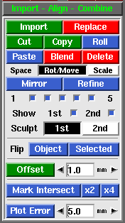 Fig 1. Import Align Combine 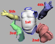 Fig 2. Mesh Colors - Import
- Load in another PLY file as a separate mesh. Fig 2 shows the different coloring applied when multiple meshes are loaded. As you can see, its possible to have many meshes loaded, but only the 2nd "red" mesh can be moved around or sculpted. To avoid confusion, its recommended that you only work with 2 meshes at a time, that is, the 1st "white" mesh and the 2nd "red" mesh.
-
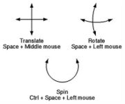 Fig 3. Postioning Meshes
- Replace
- If two meshes are loaded, a file selection window pops up, and the PLY selected will replace the 2nd mesh. If three meshes are loaded, the 2nd is deleted and the 3rd is moved into that position. This tool is normally used to substitute a hirez mesh for a decimated copy that has already been positioned in the scene.
- Cut
- Removes <G> marked faces from the 1st mesh and puts them into a new mesh at the end of the list.
- Copy
- Copies <G> marked faces into a new mesh.
- Roll
- Changes the mesh ordering by one step. If there's only 2 meshes, this swaps the 1st and 2nd meshes around.
- Paste
- Copies the faces in the 2nd mesh into the 1st mesh, then deletes the 2nd mesh.
- Blend
- Smoothly blends in faces from all the other meshes, then deletes those meshes. You will be prompted for a brush size in the 3D window; if the overlapping faces aren't intermixed that well, then you may want to increase the default brush size to make sure that faces further apart are still blended together. If the brush size is too small then you will end up with a double skin in the overlapping areas.
- Delete
- Delete all other meshes, leaving just the 1st mesh.
- Space Mode
- Normally the 2nd "red" mesh is rotated by holding <Space> then click'n'dragging the <LMB>, and moved with <Space-MMB>. For safety reasons, you can only scale the 2nd mesh by first selecting Scale next to the Space option, then use <Space-RMB> to resize.
- Mirror
- Mirrors the last mesh in the list about the Y-Z plane (i.e. its X coordinates are reversed).
- Refine
- If you need to align two meshes together that are the same shape, then the Refine tool can be used to calculate a closer fit than you could ever get my manually positioning them. You still need to roughly position them over the top of each other with <Space>, but once that's done, just click Refine. The 2nd "red" mesh is then rotated and moved around in gradually smaller amounts to get the best fit between itself and the first "white" mesh.
- The five toggle boxes underneath (numbered 1 to 5) represent the 5 stages of refinement, where 1 is the coarsest, and 5 is the most fine. The first stage is designed to be quick and dirty, pulling meshes closer together that are far apart, but sometimes this stage actually moves meshes out of alignment; this is especially a problem when there's not a lot of overlap between the two meshes. If this happens, turn off number 1 and re-run the refine. You can turn the other stages of refinement on and off for finer control over the process.
- Show
- Tick either of the boxes to show or hide the first or second meshes. You can also use the <1> or <2> hotkeys to toggle each mesh on and off.
- Sculpt
- Select which mesh is affected by the sculpting brushes.
- Flip
- Inverts the surface normals on either the 2nd "red" mesh, or the green selected faces on the first "white" mesh.
[edit] Offset
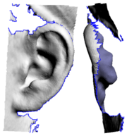 Fig 4. Missing Behind Ear Convex surfaces will balloon out, and concave surfaces will end up self-intersecting if the offset is large enough, so sometimes its a good idea to do an initial offset of about half what you think you want. You can then check the offset surface, maybe even smooth or sculpt it a bit to remove the self-intersecting faces. Click the Offset button a second time and, because you already have an offset surface created, that surface is simply push back a bit more; there's no copying of faces or flipping of surface normals.
For example, this tool can be used to add some mesh behind the ears, something that is usually missing from cylindrical type head scans (see Fig 4). 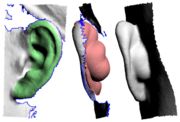 Fig 5. Offset Surface [edit] Mark Intersect
The Mark Intersect tool is used to green mark faces near the intersection of two or more objects. These marked faces could then be voided, and the gap bridged across, to join the two objects together.
The three buttons are:
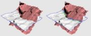 Fig 6. Before and After Mark - Mark Intersect
- When you click this button, you're prompted in the 3D window for a Tol value. Faces are then marked, at the junction between the two objects, if they are within this distance apart. See Fig 6 for a before and after image.
- Sometimes though, particularly if the tolerance value is less than the size of the faces, you'll end up with gaps in the strip of marked faces (see left side of second image). If you see this happening, or expect it will because of a low tolerance value, use either one of the following buttons.
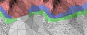 Fig 7. Fixing Gaps with x2 - x2
- This button does an initial intersection test at 2 times the tolerance value, then multiplies the faces found, then does a second intersection test at the original tolerance value. Its slower than the simple test from above, and creates more faces around the junction, but that may be be quicker in the long run than having to manually find and fix the gaps yourself. See Fig 7 for a before and after image.
- x4
- Same as above, but the initial test is done at 4 times the entered tolerance value. To be used if the faces are quite a bit larger than the tolerance value entered.
[edit] Plot Error
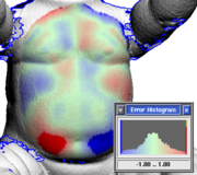 Fig 8. An Error Plot - Use the main GUI Mesh input to load one of the meshes.
- Use Import to load the second mesh.
- Use the <H> hotkey to hide parts of the meshes that might adversely affect alignment.
- If it isn't already, use <Space-LMB> and <Space-MMB> to position the second mesh closer to the first, then click on Refine to do the alignment.
- Hide the second mesh by unticking Show 2nd.
- Use the <G> hotkey to mark out the area that you want to compute the difference for.
- Set the error threshold then click on Plot Error.
A histogram window pops up, and the first mesh is re-colored in the marked area. Red is where the first mesh is over the top of the second, blue is where its underneath, and solid red/blue is where the error is greater than the threshold setting (see Fig 8).
|


