Support:UniSA
From Headus Docs

[edit] Vitronic Color Import
To import Vitronic color scans into CySize, you need to follow these steps:
- Run PlyTool as you normally would.
- Tick the "UV to CPV" option (see Fig 1).
- Click the arrow and load the first color texture file.
- Set the rotation angles to 90, 0, 90.
- Click the Input arrow and load the OBJ file with Meters ticked (see Fig 2). Even if you already have an OBJ loaded, you need to reload it after ticking the "UV to CPV" option.
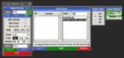 Fig 2. Load OBJ
 - Click the Output arrow and specify the PLY file as you normally would.
- Click Convert
- Click View, and use the 'C' key to shade the mesh with color to check the conversion.

Load the PLY file into CySize and process as you normally would and the color should end up in the final merged and filled surface. You can then use the "Place Landmarks" tool to quickly place points on all of your color markers.
[edit] Bounding Measure Method
 Fig 3. Determine Axis The first step is to determine the axis of the bounding volume. Another way to look at it could be the direction of travel that the object would be moving in. By default its the direction defined by the start and end points of of the section guide curve, and this is illustrated in the middle image in Fig 3. The right image shows the difference in slicing direction for a Z-axis tagged section.  Fig 4. Cut Sections Next the mesh is sliced through, perpendicular to the bounding axis, and all these slices are then moved along the bounding axis so that they are co-planar (see Fig 4).  Fig 5. Convex Hull Finally the convex hull of the gathered slices is calculated (see Fig 5), and this profile is then projected back along the bounding axis to create the blue volume displayed in the software. |